Using direct attached FC storage with UCS has been supported for a good while by Cisco and most hardware manufacturers but with one major caveat, you needed to have an MDS, Nexus, Brocade or some other FC switch upstream to house the zoning database as the fabric interconnect did not have the capability to do zoning services. While this would work it wasn't always the most cost effective method of deploying storage to a UCS environment due to the fact that you had to utilize FC ports on the Fabric Interconnect for the front end ports on the storage array and for the fiber switches. Not to mention the additional management overhead of additional hardware north of the fabric interconnects. This is what a typical setup would look like before we had UCSM firmware version 2.1x.


With the introduction of firmware version 2.1(1a) Cisco has introduced UCSM based FC zoning for direct connected topologies. This eliminates the need to have an upstream switch host the FC zoning database as the zoning can be handled within the Fabric Interconnects. It's not difficult to setup and it works great. In my setup I have an EMC VNX 5300 and a pair of 6296 Fabric Interconnects. Connectivity from the VNX front end storage ports to the FI's is diagrammed below:

Configuring the zoning is pretty straight forward in the UCSM and all configuration is done in the SAN tab on the UCSM. The first step is to create your VSAN's. I do not use the default VSAN (VSAN1) for production traffic per Cisco's best practice. Since we have a dual Fabric Interconnect configuration, we'll configure 2 VSAN's. Fabric Interconnect A will be VSAN 15 and Fabric Interconnect B will be VSAN 25. You can pick any numbers want, just make sure they don't fall into the restricted range for named VSAN ID's. Refer to the Cisco UCS Manager GUI Configuration Guide, Release 2.1 for more information on the restricted VSAN ID's.
Step 1 - Creating a VSAN in UCSM:
In the SAN tab under Storage Cloud, right click on VSANs and select Create Storage VSAN. The following window will appear.

Repeat the process to create VSAN25. You now have 2 VSAN's created with zoning enabled.
Step 2 - Create a Storage Connection Policy
The Storage Connection policy is what defines your storage targets within UCS. It's simply a list of WWPN targets that the FI's will put into zones with the WWPN's of the vHBA's just like a normal FC switch.
To create a Storage Connection Policy, right click on Storage Connection Policy and select Create Storage Connection Policy. The following window will appear.

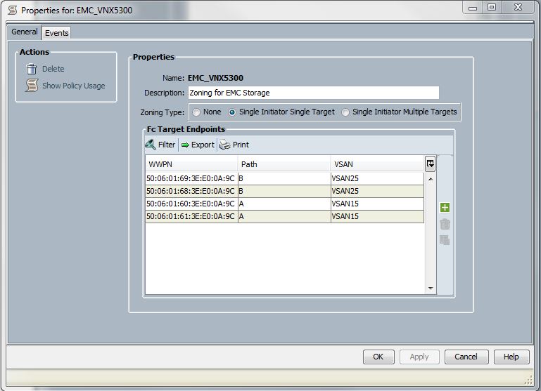
Enter a name and description for the Storage Connection Policy. Press the green + button on the right to enter the target and fabric information for the storage. On the VNX, you can get the WWPN info for the SP ports from within Unisphere Manager.

Once all 4 FC front end target ports have been entered into the storage connection policy, it should look like this:
Step 3 - Create vHBA Templates
Create your vHBA Templates as you normally would in a UCS deployment. Ensure that each HBA you create is assigned to a particular VSAN. In this case, we're creating 2 templates. One for fabric A and one for fabric B for redundancy and fail over. Fabric A vHBA will be assigned to VSAN15 and Fabric B vHBA will be assigned to VSAN25.
Repeat the process for the second vHBA Template on Fabric ID B on VSAN25
Step 4 - Create Service profile Template
Create a service profile template with all other Server, LAN, and SAN policies you require for your server. There is a section on zoning we'll focus on that requires special configuration that will mate the vHBA's in the service profile to the storage targets we specified earlier in the Storage Connection Policy.
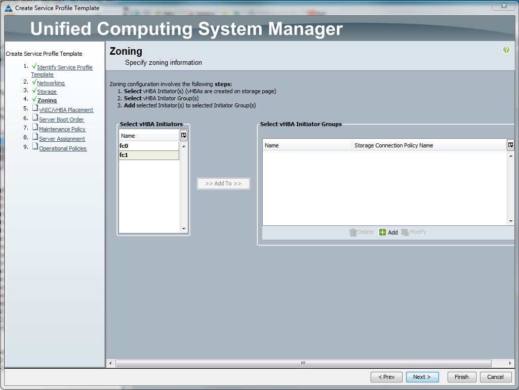
In the storage portion of the Service Profile Template creation, it asks to create a vHBA. I chose expert mode and created 2 vHBA's each using the 2 vHBA templates we created earlier. I named each vHBA fc0 and fc1. fc0 uses vHBA template A (using fabric interconnect A as it's path (VSAN15)) and fc1 uses vHBA template B (using fabric interconnet B as it's path (VSAN25)).
Next, it asks you to configure initiator group. This is just a container that houses the 2 vHBA's we created earlier. Here's the screen you immediately after creating the vHBA's.
Select the green + button to create a new vHBA Initator Group. Enter a name and description. Under Storage Connnection Policy, select the dropdown to select the policy we created earlier for the VNX_5300.
Select OK and you'll now see a new initiator group in the right hand box to which you can add the newly created vHBA's to. You must first highlight the initiator group name on the right to enable the Add To button. Once it's clickable you can select both fc0 and fc1 from the left box, select Add To and the vHBA's will be placed in under the initiator group.
The rest of the work is standard issue service profile template configuration going through the wizard. Once the service profile template is associated to a server the server can be fired up and the zoning information can be viewed through the UCSM. Under the Service Profile and for a particular server, go to the FC Zoning tab and you'll see the zones that are created inside the Fabric Interconnects.
I’m satisfied with the information that you provide for me and thanks for this because sometimes people face this problem.
ReplyDelete